Traffic light state diagram
This traffic light state diagram shows a single signal moving through three states, **Red**, **Green** and **Yellow**, in a fixed loop driven by a timer. It is useful for students learning UML state machines and for developers modelling simple timed controllers.
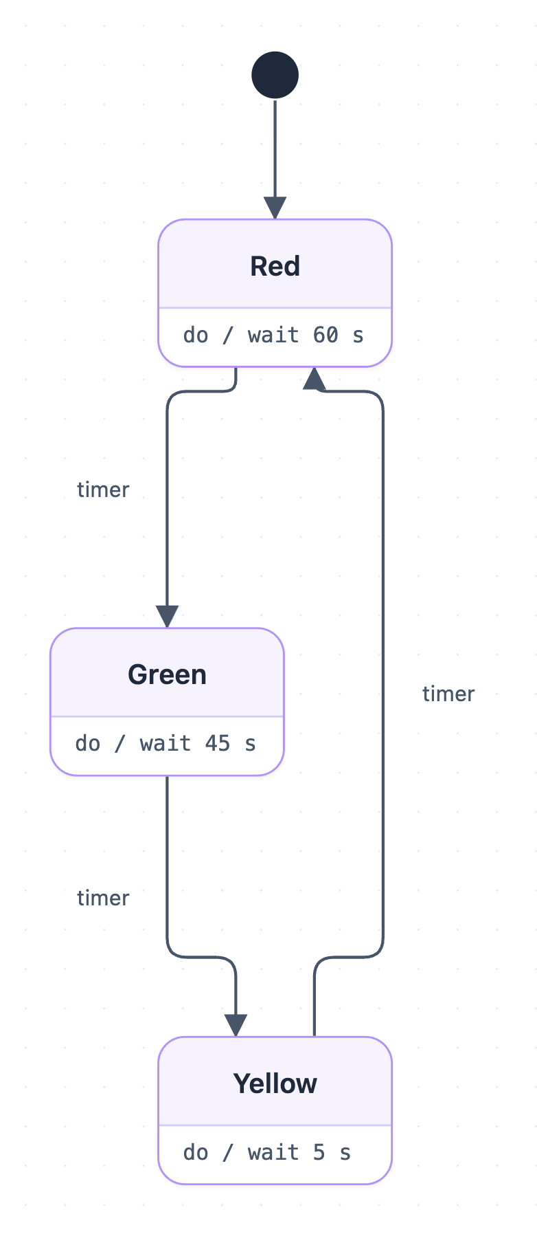
Example: State diagram for a traffic light: click to open it in the editor and change it.
The states
The diagram has one start point and three states. Each state has a do action, which is an activity that runs for as long as the light stays in that state.
| State | Do action | Meaning |
|---|---|---|
| Red | do / wait 60 s | Traffic must stop for 60 seconds |
| Green | do / wait 45 s | Traffic may go for 45 seconds |
| Yellow | do / wait 5 s | Warning before red, lasting 5 seconds |
Transitions in order
- The start node (initial pseudostate) leads straight into Red, so the light always begins on red.
- Red → Green on the timer event, after the 60-second wait ends.
- Green → Yellow on the timer event, after 45 seconds.
- Yellow → Red on the timer event, after 5 seconds, and the cycle repeats.
There is no final state. The machine loops forever, and one full cycle takes 110 seconds (60 + 45 + 5).
How to adapt it for your project
- Change the wait times in each do action to match local rules or a busier road.
- Add a pedestrian request event, such as a button press, that shortens Green or adds a walk state.
- Add a separate flashing-yellow or off state for night mode or faults, with its own trigger events.
- Model a second light for the crossing road and keep the two machines in sync.
- Open and edit it to rename states, add guards like [car waiting], or attach entry/exit actions.
Tip: Keep events (like timer) on the arrows and activities (like wait 60 s) inside the states. Mixing them up is the most common mistake in state diagrams.
Frequently asked questions
What are the states in a traffic light state diagram?
This diagram has three states: Red (60 s), Green (45 s) and Yellow (5 s), plus an initial start node that enters Red first.
What triggers the transitions between traffic light states?
Every transition is triggered by a timer event that fires when the current state's wait time has passed. The order is Red to Green, Green to Yellow, and Yellow back to Red.
Why does the traffic light state diagram have no final state?
A traffic light runs continuously, so the states form an endless loop. You only need a final state if you model the light being switched off.
Make your own state diagram with AI →